Requirements of a Circuit
Suppose that you were given a small light bulb, an electrochemical cell and a bare copper wire and were asked to find the four different arrangements of the three items that would result in the formation of an electric circuit that would light the bulb. What four arrangements would result in the successful lighting of the bulb? And more importantly, what does each of the four arrangements have in common that would lead us into an understanding of the two requirements of an electric circuit?
The activity itself is a worthwhile activity and if not performed before, one ought to try it before reading further. Like many lab activities, there is power in the actual engagement in the activity that cannot be replaced by simply reading about it. When this activity is performed in the physics classroom, there are numerous observations that can be made by watching a class full of students eager to find the four arrangements. The following arrangements are often tried and do not result in the lighting of the bulb.
After a few minutes of trying, several healthy chuckles, and an occasional exclamation of how hot the wire is getting, a couple of students become successful at lighting the bulb
Light Bulb Anatomy
Once one group of students successfully lights the bulb, many other lab groups quickly follow suit. But then the question emerges as to what other ways that the cell, bulb and bare wire can be arranged in such a manner as to light the bulb. Often a short light bulb anatomy lesson prompts the lab groups into a quick discovery of one or more of the remaining arrangements.
The Requirement of a Closed Conducting Path
There are two requirements that must be met to establish an electric circuit. The first is clearly demonstrated by the above activity. There must be a closed conducting path that extends from the positive terminal to the negative terminal. It is not enough that there is simply a closed conducting loop; the loop itself must extend from the positive terminal to the negative terminal of the electrochemical cell. An electric circuit is like a water circuit at a water park. The flow of charge through wires is similar to the flow of water through the pipes and along the slides at a water park. If a pipe gets plugged or broken such that water cannot make the complete path through the circuit, then the flow of water will soon cease. In an electric circuit, all connections must be made and made by conducting materials capable of carrying charge. As the cell, bulb and wire experiment continues, some students explore the capability of various materials to carry a charge by inserting them in their circuit. Metallic materials are conductors and can be inserted into the circuit to successfully light the bulb. On the other hand, paper and plastic materials are typically insulators and their insertion within the circuit will hinder the flow of charge to such a degree that the current ceases and the bulb no longer lights. There must be a closed conducting loop from the positive to the negative terminal in order to establish a circuit and to have a current.
Electric Circuits Review
A water ride at a water park is analogous to an electric circuit. First of all, there is an entity which flows – water flows in a water park and (in conventional terms) + charge flows in an electric circuit. In each case, the fluid flows spontaneously from a high energy location to a low energy location. The flow is through pipes (or slides) in a water park and through wires in an electric circuit. If the pipes or the wires are broken, then there can be no continuous flow of fluid through the circuit. A complete loop is required to establish the circuit.
This flow of fluid – whether of water or charge – is possible when a pressure difference is created between two locations in the circuit. In the water park, the pressure difference is the difference in water pressure created by two locations of different heights. Water flows spontaneously from locations of high pressure (high altitude) to locations of low pressure (low altitude). In an electric circuit, the electric potential difference between the two terminals of a battery or energy source provides the electric pressure which presses on charge to move them from a location of high pressure (high electric potential) to a location of low pressure (low electric potential).
Energy is required to move the fluid uphill. In a water park, a water pump is used to do work upon the water in order to raise it from the low height back up to the high height. The water pump does not supply the water; the water which is already in the pipes. Rather, the water pump supplies the energy to pump the water from the location of low energy and low pressure to the location of high energy and high pressure. In an electric circuit, the battery is the charge pump which pumps the charge through the battery from the location of low electric potential energy (the – terminal) to the location of high electric potential energy (the + terminal). The battery does not supply the electric charge; the charge is already in the wires. The battery simply supplies the energy to do work on the charge in pumping it uphill.
The flow of water at a water park is analogous to the flow of charge in an electric circuit. The rate at which charge moves past a point on a circuit as measured in Coulombs of charge per second (or some comparable set of units) is known as the current. In our analogy, the fluid which flows is water and the rate at which the fluid passes any given point is the current.
Electric Circuit Studio | User Guide
Electric Circuit Studio (ECStudio) is a set of tools used for building electronic circuits, SPICE simulation, and calculation of circuits. These tools are complemented by the information center containing resources, connector pinouts and interactive book explaining basic electrical theorems, laws and circuits. It is a useful application for all electronics hobbyists, students, or other people with an interest in electronics.
Schematic editor and SPICE simulator allow easy creation of circuit diagrams and SPICE analysis of the created circuits. ECStudio simulator is focused on visual representation of simulated results, such that simulated voltages and currents can be placed elsewhere in the circuit, as a text or graph. Moreover, the magnitude and polarity of voltages and currents can be represented by visual indicators, so you can check the results quickly. All results can be additionally displayed on the top plot, where they can be explored using two cursors.
DC, AC and Transient analyses are supported. The simulation can be run repeatedly (in Transient analysis) and results can be displayed consecutively with a user controlled speed (in all analysis types), or all simulation results are displayed immediately. When the results are shown consecutively, you can control parameters of circuit elements by the seek bar and see the change of results in real time.
The application supports two modes: Normal and Restricted. The Restricted mode differs from the Normal mode in that the size of the drawing canvas is restricted to the size of the circuit, elements cannot be inserted, moved, rotated, flipped or deleted, and the undo, redo, saving and opening circuits are not allowed. This mode is intended to be used only for simulation of circuits.
Important notes:
The app internally uses industry standard SPICE program of version 3.
Electrical Circuits: Dressing smart
Electrical circuits are everywhere in the modern world – hidden in the walls of our houses and packed inside our phones, computers and cars. Engineers are now working at knitting circuits into our clothes so we might one day wear devices that continuously monitor our health.
Electronics are everywhere. And as older people like to say, young people today are “digital natives” – you’re confident and competent with computers, smartphones, and any other electronics devices thrown at you. It’s likely you’ve had to give a grandparent or neighbour advice on how to use a computer or the car navigation yourself!
But when it comes to the clothes on your back there’s not much that your grandparents wouldn’t recognize – apart from the fashion, maybe. There are cotton, silk and woollen garments just as there have been for hundreds of years, and synthetic fibres have been around for over a century now.
But the electronics geeks have their eyes on your threads now, too, with scientists working on ways to integrate electronics into fabrics.
For a start, they envisage building in sensors. These would monitor the forces your muscles are exerting, impacts on your body, and your temperature, heart rate and respiration. This information could be recorded for later use or be set up to trigger a warning, if needed. Some fabrics might even be clever enough to react, for example stiffening up to give you extra support when your muscles are straining.
How to Choose the Right Resistor
Everything You Need to Know to Choose the Right Resistor for Your First PCB Design Project
Planning to embark on your first PCB design software project? There’s a ton of components that you’ll end up using, but none can beat the infamous of them all – the simple resistor. If you have ever looked at a circuit board, you’ll find resistors are all over the place, controlling the current flow and making those LEDs light up. But what exactly is a resistor, how does it work, and how in the world do you choose the right one for your first PCB design project? Fear not, we have you covered with everything you might need to know.
So…What is a Resistor?
Resistors are one of several passive electrical components, and their job is relatively simple yet vital – creating resistance in the flow of an electric current. Have you ever seen a LED light up? That was made possible thanks to the trusty resistor. By placing a resistor behind a LED in a circuit, you get all of the brilliant lights without anything burning out!
What Kind of Resistors Are There?
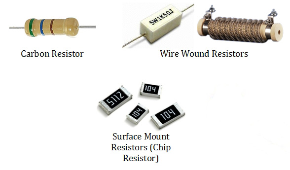
There’s a ton of resistors floating about that are divided into two categories – construction type and resistance material
Fixed Resistors – As the name implies, these resistors have a fixed resistance and tolerance regardless of any changes in temperature, light, etc.
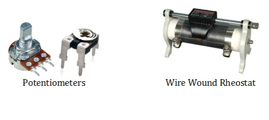
Variable Resistors – These parts have a modifiable resistance. The potentiometer is a great example, which has a dial that can be turned to ramp up or down the resistance. Other variable resistors include the trimpot and rheostat.